1.
Chemical Vapor Deposition (CVD): Carbon source gases typically used include hydrocarbons such as ethylene and methane, while metal catalysts such as iron, nickel, cobalt, etc., are usually chosen for the catalyst. The substrate to be deposited (e.g., silicon wafer, glass wafer, etc.) is placed in a reaction chamber to ensure that the substrate surface is clean and flat. The reaction chamber is heated to an appropriate temperature and then extracted to a certain vacuum level to ensure the purity and stability of the gases during the reaction process. The carbon source gas and catalyst gas are introduced into the reaction chamber through a gas supply system to control the gas flow rate and flow volume. The carbon source gas dissociates on the catalyst surface to generate carbon atoms, which are subsequently deposited on the substrate surface to form carbon nanotubes. The growth time of the carbon nanotubes is controlled, usually ranging from minutes to hours, to control the length and density of the nanotubes. Prolonged growth results in longer and denser carbon nanotubes. At the end of growth, the supply of carbon source and catalyst gas is stopped and the reaction chamber is cooled to room temperature. At the end of the reaction, the residual gas in the reaction chamber is removed by supplying an inert gas such as nitrogen or argon.
2. Coating Method: The carbon nanotube suspension is coated on the substrate surface by spin-coating, spraying, brushing, or rolling. During the coating process, parameters such as the coating speed and the rotation speed of the coating head can be controlled to control the thickness and uniformity of the film. After coating, the coating is placed in a ventilated area or on a heated bench to induce solvent evaporation. After the solvent has evaporated completely, drying is performed to form a uniform carbon nanotube film. Optionally, the carbon nanotube film is heat-treated to improve the crystallinity and mechanical properties of the film. The heat treatment conditions can be adjusted as needed and are usually performed under an inert gas atmosphere.
3. Filtration: Commonly used filter membrane materials include polycarbonate (PC), polyester (PET), and polyamide (Nylon) membranes, while the pore size is usually selected based on the desired film thickness and permeability. The carbon nanotube suspension is filtered onto the filter membrane by vacuum or pressure. Filtration operations can be performed using equipment such as vacuum filtration funnels or membrane filters.
4. Stripping Method: common stripping methods include mechanical stripping, where the carbon nanotube film is directly stripped from the substrate using stripping tools (e.g., tapes, scrapers, etc.); chemical stripping, where the grown carbon nanotube film is placed in an appropriate solvent or solution so that the bond between the film and the substrate is damaged to realize the stripping; and thermal stripping, where the substrate or the film is heated to make it thermally expanded or contracted to destroy the bond between the substrate and the film to realize the stripping; and thermal stripping, where the substrate or the film is heated to make it thermally expanded or contracted to destroy the bond between the substrate and the film to realize the stripping. and the film by heating the substrate or the film, causing it to expand and contract thermally, thereby breaking the bond between the substrate and the film.
5.3.3 Case Study: Carbon Nanotube-Enhanced Reverse Osmosis Membranes
A unique application of carbon nanotubes, in addition to functional applications similar to other types of filtration membranes, is reverse osmosis membranes. This membrane separation technology is capable of separating impurities, ions, microorganisms, etc. from water, which is widely used in the fields of drinking water, industrial wastewater treatment, and seawater desalination. However, reverse osmosis membrane has the problem of low flux and low processing efficiency. To solve this problem, scholars introduced carbon nanotubes into reverse osmosis membranes. Carbon nanotubes have excellent properties such as high specific surface area, high strength, high conductivity, etc., which can form a kind of proton conductor channel in the reverse osmosis membrane and increase the flux. At the same time, carbon nanotubes can also adsorb ions microorganisms, and other impurities in water, which can effectively improve the water purification efficiency and life of the reverse osmosis membrane. At present, reverse osmosis membrane based on carbon nanotubes has been put into commercial use, in the field of drinking water, seawater desalination, and other areas to obtain significant results. In the future, the research and preparation technology of carbon nanotube materials will be further developed, and the flux and processing efficiency of reverse osmosis membranes will be continuously improved.
Table 2 Comparison of TiO2 Nanotube, GO, and CNT Properties
|
Properties
|
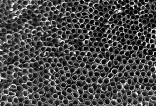
Titanium Dioxide (TiO2) Nanotube Membranes
|
Graphene Oxide (GO) Membranes
|
Carbon Nanotube (CNT) Membrane
|
|
Material Structure
|
Titanium oxide nanotubes
|
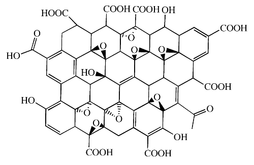
Graphene oxide with oxygen-containing functional groups
|
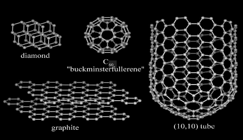
Carbon nanotubes
|
|
Preparation Method
|
Solution method Vapor deposition method Electrochemical method
|
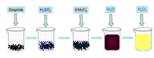
Coating method Chemical vapor deposition method Hydrothermal method
|
Chemical vapor deposition Coating method Filtration method
|
|
Application Areas
|
Photocatalysis Photovoltaic devices Water and air purification
|
Water treatment Air purification Molecular separation Biomedicine
|
Water treatment Reverse osmosis membranes Molecular separation Biomedicine
|
|
Advantages
|
High surface area Special photovoltaic properties Photocatalytic activity
|
Many oxygen-containing functional groups High surface activity Molecular selectivity
|
High strength High conductivity High specific surface area Adjustable performance
|
|
Drawbacks
|
Complex preparation process and high-cost
|
Prone to structural defects and poor stability during the preparation process
|
Complex preparation process High process control requirements
|
|
Applications
|
Photocatalytic water treatment Air purification Photovoltaic device preparation
|
Water treatment Molecular separation Biomedical applications
|
Reverse osmosis membranes Molecular separation Biomedical applications
|
6 Metal Organic Framework (MOF)-based Membranes
6.1 What Are MOF Membranes
Metal Organic Framework (MOF), is a coordination polymer made by self-assembly of polydentate organic ligands containing oxygen, nitrogen, etc. with transition metal ions. It consists of inorganic metal centers and bridging organic ligands connected through self-assembly to form a crystalline porous material with a periodic network structure. As an organic-inorganic hybrid material, MOF has both the rigidity of inorganic materials and the flexibility of organic materials.
The backbone-type structures in different dimensions are mainly determined by the coordination between organic ligands and metal ions as well as hydrogen bonding. During the synthesis process, residual reactants and small molecules of solvents occupy the pores of the skeleton structure, while the removal of small molecules by activation treatment can leave a persistent pore structure. The size and structure of the pores can be altered by changing the structure of organic ligands and the type of metal ions in the synthesized feedstock to control the specific surface area and porosity to suit different applications. At present, metal-organic skeleton materials used together with nitrogen-containing heterocyclic organic neutral ligands or with carboxyl-containing organic anionic ligands can be synthesized in large quantities, which presents great potential for development and application in modern materials research.
6.2 How to Produce MOF Membranes
1. In-situ synthesis method: according to the special surface properties of the carrier itself, the carrier is directly put into the synthesis system, and under certain conditions, the carrier surface and the film-forming night directly contact and thus react, to prepare a continuous membrane. The in-situ synthesis method is simple and easy to operate, easy to realize large-scale production, but it is difficult to prepare continuous MOF membrane, because the chemical properties between MOF materials and carriers are more different, the rate of crystal nucleation is reduced, resulting in low density of heterogeneous nucleation of MOF crystals on the surface of the carrier, and poor bonding between the membrane and the carrier.
2. Crystal seed secondary growth method: first use the hydrothermal method to make the crystal seed grow on the substrate, and then after the process of crystal nucleation, membrane layer growth, the material secondary growth for dense membrane. Finally, the porous substrate surface crystal species after high temperature, the condensation reaction between the groups, and zeolite grains combined to form covalent bonds. However, the method is somewhat limited because the filter membrane does not withstand high temperatures.
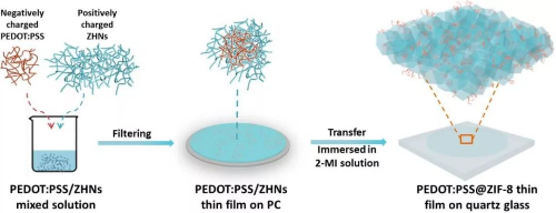
Fig. 10 Schematic Synthesis of a MOF Film: PSS@ZIF-8 Film
6.3 Specialized Application in Heavy Metal Removal
In addition to functional applications similar to other types of filtration membranes, MOF membranes can be applied to the treatment of heavy metal ions. MOF membranes have a highly ordered porous structure formed by metal ions and organic ligands through ligand chemical bonding. This porous structure has a tunable pore diameter and pore size, providing many adsorption sites and channels, which are favorable for the adsorption and embedding of heavy metal ions. This enables MOF films to be used in the field of water treatment, such as the removal of heavy metal ion pollutants, such as lead, cadmium, and mercury, from groundwater, industrial wastewater, and municipal wastewater. The highly controllable pore sizes and surface functionalization of MOF films allow for efficient adsorption and selective separation of specific heavy metal ions. It also plays a role in adsorption treatment and recovery for environmental remediation and wastewater treatment processes. MOF films can realize efficient capture and recovery of target metals during heavy metal ion adsorption. Through appropriate post-treatment methods, the adsorbed heavy metal ions can be desorbed from the MOF film, realizing the effective recovery and reuse of metal resources.
7 Composite Filter Membrane
Composite filter membranes are different from traditional single-material filter membranes in that they combine two or more materials to give full play to their respective strengths and make up for each other's deficiencies, thereby achieving more efficient and reliable filtration. These materials can include polymers, ceramics, metals, nanomaterials, etc. Each material has unique physical, chemical, and mechanical properties and can be flexibly combined according to different filtration requirements.
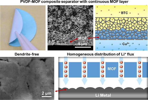
In lithium-ion batteries, a PVDF-MOF Composite Membrane with a continuous MOF layer serves as a high-performance diaphragm. The uniform pore structure and sub-nano channels with connected open metal sites in the continuous MOF layer can generate uniformly distributed Li+ flux, inhibit the formation of dendritic protrusions, and improve electrochemical performance.
Fig. 11 PVDF-MOF Composite Separator with Continuous MOF Layer [5]
In the field of seawater desalination, membrane distillation (MD) has emerged as an alternative seawater desalination strategy that can largely reduce capital costs and energy consumption. In the MD process, almost 100% of the nonvolatile are removed and there is no limitation on the feed water concentration, whereas the pressure-driven reverse osmosis (RO) process has less potential for treating high salinity solutions with low water recovery. Volatile components are separated from the feed mixture utilizing a microporous hydrophobic membrane, and the system operates below the boiling point of the feed liquid. For MD applications, polymeric materials with low surface energy, high thermal stability, chemical stability, and inertness are often preferred. Polytetrafluoroethylene (PTFE) and Polyvinylidene Fluoride (PVDF) are considered the primary commercially available membrane materials for Vacuum Membrane Distillation (VMD) due to their high thermal stability and hydrophobicity. PVDF and PTFE are the optimal polymers for VMD applications due to their excellent chemical resistance and durability. These properties allow PVDF to withstand the aggressive chemical environments often encountered in VMD systems, ensuring long-term operational reliability. PTFE, on the other hand, plays a key role with its non-stick properties and excellent resistance to high temperatures. In VMD, PTFE helps improve membrane performance and effectively prevents fouling, thus ensuring unobstructed and efficient vapor transport throughout the membrane during distillation. In VMD applications, the synergistic use of PVDF and PTFE improves the durability, chemical resistance, and operational efficiency of the overall membrane system.
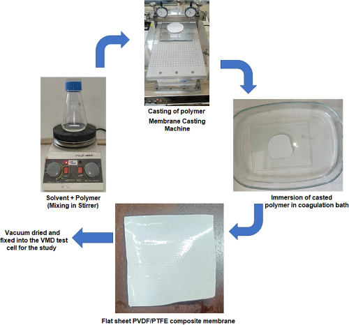
Fig. 12 Flow Chart on Preparation of Microporous PVDF-PTFE Composite Membrane [6]
8 Conclusion
Filter membranes made of different materials are used in different fields due to their different characteristics and can be selected according to different needs in addition to the basic filtration process. PVDF membranes can be used to filter microorganisms such as bacteria, and can also be used for material purification in chemical production; ceramic membranes are mostly used in the food industry for the separation of alcoholic beverages; titanium dioxide nanotube membranes can be used for related applications and the treatment of heavy metal ions due to their photocatalytic properties; graphene oxide membranes can be used for molecular separation, as well as for desalination of seawater and separation of oil and water; carbon nanotubes can be used as reverse osmosis membranes; and MOF membranes can be used to selectively separate heavy metal ions due to the nature of the coordination compounds. In addition, according to the needs of different application scenarios, different types of filtration membranes can be used in conjunction with each other, and the composite type of membrane can achieve a better filtration effect by complementing the characteristics of different types of material filtration membranes.
Stanford Advanced Materials (SAM) can not only provide a wide range of filtration membrane products but also provide professional selection advice, which you can
consult immediately.
Related Reading:
References:
[1] Khayet M ,Feng C ,Khulbe K , et al. Preparation and characterization of polyvinylidene fluoride hollow fiber membranes for ultrafiltration[J]. Polymer,2002,43(14).
[2] Li M ,Cheng S ,Zhang J , et al. Poly(vinylidene fluoride)-based composite membranes with continuous metal–organic framework layer for high-performance separators of lithium-ion batteries[J]. Chemical Engineering Journal,2024,487.
[3] Hu W ,Zhang F ,Tan X , et al. Antibacterial PVDF Coral-Like Hierarchical Structure Composite Film Fabrication for Self-Cleaning and Radiative Cooling Effect.[J]. ACS applied materials & interfaces,2024.
[4] Wei Y ,Li K ,Li P , et al. Enhanced ceramic membranes filtration by PS pre-Oxidation with CuO assisted FeSO4 catalytic for NOM removal in drinking water treatment[J]. Separation and Purification Technology,2024,345.
[5] Ceramic membranes and their application in food and beverage processing[J]. Filtration and Separation,2000,37(3).
[6] Mala M M ,S. S ,S. F , et al. Sea and brackish water desalination through a novel PVDF-PTFE composite hydrophobic membrane by vacuum membrane distillation[J]. Discover Chemical Engineering,2024,4(1).
