A Comparison between Tantalum and Multilayer Ceramic Capacitors
Introduction
Tantalum (Ta) capacitors and multilayer ceramic capacitors (MLCC) are two widely used capacitors in electronic applications. Though the construction technologies and materials for tantalum capacitors and MLCCs are quite different, their basic functions are still the same. Acting as a temporary battery, capacitors maintain constant DC voltage by providing charges. Capacitors can also be used in bypass channel circuits as single pole filters. They can even connect with resistors and inductors to make high-order filter circuits.
Although tantalum capacitors and MLCCs work both as capacitors, they do have many differences from manufacturing to their parameters during use. Before introducing their differences, let’s first get some basic information about capacitors. For a parallel-plate capacitor, its capacitance value should be calculated by the following equation.

C = εr*ε0*A/d
C = capacitance (F)
A = the area of overlap of the two plates (m2)
εr = the relative permittivity/ dielectric constant (εr is determined by the material between the plates)
ε0 = the electric constant (8.854 * 10-12 F*m-1)
d = the distance between two plates (m)
Capacitance is one of the important parameters when people consider choosing which kind of capacitor. Because of the small distance, large plate areas and high Ta2O5 dielectric constant, tantalum capacitors usually have large capacitance values/ volume.
This article will compare tantalum capacitors and MLCCs in these aspects: the impedance curve, parasitic inductance (ESL), equivalent series resistance (ESR), temperance effects, and microphonic effects. All comparisons are limited to capacitors with similar capacitance and size.
Basic Information on Tantalum and MLCC Capacitors
What is Tantalum Capacitor?
Tantalum capacitors use tantalum powder and wires as their feedstock. By pressing tantalum powder around a tantalum wire, a tantalum pellet is formed. This tantalum pellet is the anode for the capacitor. Since the pellet is very porous, it allows lots of charges to be collected. This is one reason for the high capacitance/ volume of tantalum capacitors. By forming Ta2O5 outside the anode, a dielectric forms. The last step is to form a cathode outside the dielectric by using Mn(NO3)2 to make the MnO2 cathode layer.
Figure 1a is a traditional tantalum capacitor using a tantalum wire to connect the anode to the circuit. Figure 1b is a new, small tantalum capacitor that is introduced to the market in recent years. It is often used in high component density environments and limited room board space. Its anode is made by pressing a tantalum wafer with tantalum powder [2].
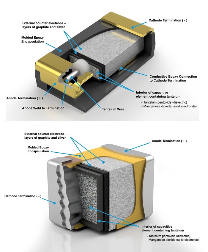
Figure 1a & b: a molded style tantalum capacitor (top) and a microchip-style tantalum capacitor (bottom) [2]
What is a Multilayer ceramic capacitor?
Unlike tantalum capacitors, ceramic capacitors have a thicker layer and a smaller overlapping plate area, which means smaller capacitance/ volume. TiO2 and BaTiO3 are the two most popular materials used in MLCCs. Figure 2 shows you the components of an MLCC.
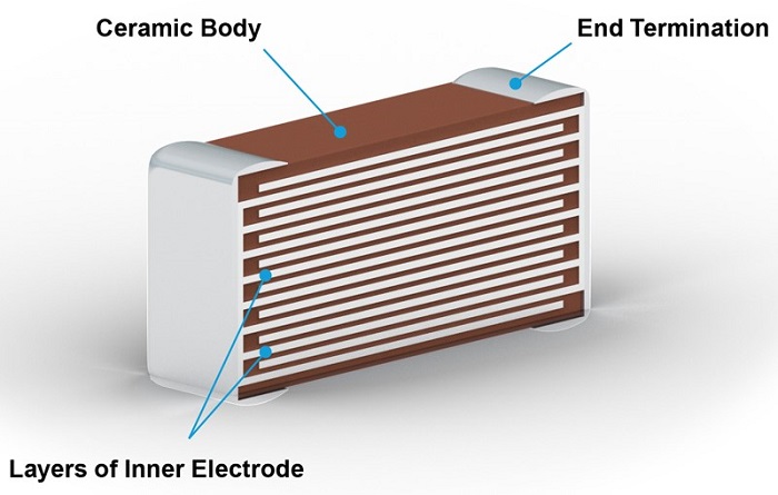
Figure 2: A multilayer ceramic capacitor [2]
Among MLCCs, there are 2 different groups: class 1 and class 2. Class 1 ceramic capacitors use ceramic materials that are not sensitive to temperature changes. Therefore, their capacitance will not change significantly from a low temperature to a high temperature such as from -25℃ to 80℃. Class 1 capacitors are usually made by TiO2 and have relatively low εr.
In contrast, class 2 capacitors are sensitive to temperature. They are made from ferroelectric materials such as BaTiO3, Al2SiO5, and MgO:XSiO2. Class 2 capacitors have relatively high εr but low accuracy and stability.
Ceramic capacitors use the EIA code to show capacitors’ stability over a temperature range. Figure 3 shows each code mean. For example, X7R means the capacitance varies ±15% from -55℃ to 125℃.
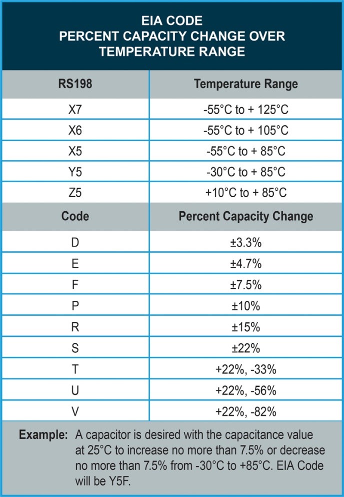
Figure 3: EIA code table [2]
What is the Difference Between Tantalum Capacitors and MLCCs?
Impedance and equivalent series resistance
The impedance, the parasitic inductance (ESL), and the equivalent series resistance (ESR) can tell lots of information about how well the capacitor works. ESL and ESR can be calculated by impedance analyzers. Smaller ESL and ESR mean better capacitors. Figure 4 shows the impedance and ESR for 4.7µF, Y5V, 16V MLCC and a 4. 7µF, 16V tantalum capacitor [1].
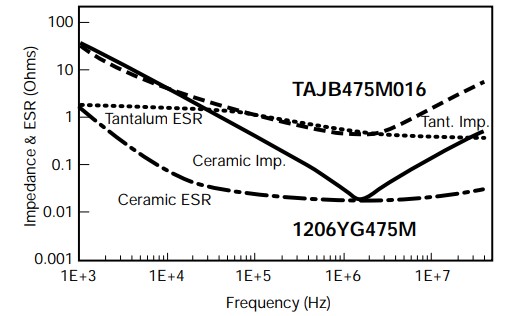
Figure 4: Impedance and ESR curves for 4.7uf tantalum and ceramic capacitors [1]
At low frequencies, their impedances are the same, which means their capacitance values are the same. As Frequency increases, the ESR of the ceramic capacitor is much lower than that of the tantalum capacitor. As for the impedance curves, both show a “V” shape that decreases first and then increases. The first decreasing part is affected by the increase in capacitive value. Then, inductive constitution (ESL) takes place and moves the impedance curve right up. Back to Figure 4, the ESL of the ceramic capacitor is much smaller than that of the tantalum capacitor by looking at the end of impedance curves. This is mainly caused by the lead frames used in the tantalum package [1].
Temperature effects
As mentioned before, Class 1 ceramic capacitors are insensitive to temperature, while Class 2 ceramic capacitors are temperature sensitive. Figure 5 illustrates that the capacitance of tantalum capacitors has a linear relationship with temperature, while the capacitance of Class 2 ceramic capacitors has an irregular relationship with temperature.
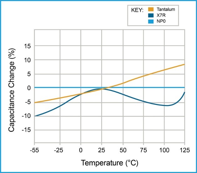
Figure 5: Capacitance change vs. temperature for Ta, Class 1 ceramic, and Class 2 ceramic capacitors [2]
Microphonic effects
When capacitors are used in audio applications, the microphonic or piezoelectric effect becomes one of the important features when selecting capacitors [1]. BaTiO3, which is widely used in MLCCs, shows microphonic effects. However, tantalum capacitors show no microphonic effects. By testing 1µF capacitors, we get Figure 6, which further confirms that Class 2 ceramic capacitors give microphonic effects.
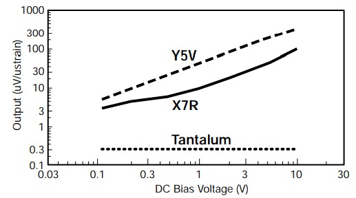
Figure 6: Microphonic effect of tantalum and ceramic capacitors [1]
Conclusion
There is no simple answer to tell which capacitor is better as both are good choices. Tantalum capacitors have a longer lifetime, higher capacitance/ volume and higher stability; MLCCs have lower inductance and ESR. You can choose according to your specific application. The table below lists the differences between tantalum capacitors and multilayer ceramic capacitors.
Parameter | Tantalum | Ceramic |
ESR |
| ü |
ESL |
| ü |
Impedance |
| ü |
Capacitance/ volume | ü |
|
Temperature | ü |
|
microphonic | ü |
|
lifetime | ü |
|
Price |
| ü |
Stanford Advanced Materials (SAM) provides both tantalum capacitors and multilayer ceramic capacitors. If you still have difficulty in choosing which capacitor, you can provide your application information to our technical staff for advice.
Reference:
Cain, J. (n.d.). Comparison of Multilayer Ceramic and Tantalum Capacitors.
Zedníček, T. (2022, June 1). The basics & benefits of tantalum vs ceramic capacitors. Passive Components Blog. Retrieved January 11, 2023, from https://passive-components.eu/the-basics-benefits-of-tantalum-ceramic-capacitors/

